Guide
Rebar vs Wire Mesh for a Concrete Slab
Mesh and rebar compared for slabs on ground: what each does, how each is named, where it goes, and a worked steel count.
By the Yardwork editorial team · Published
Welded wire mesh and rebar both put steel inside a concrete slab, but they come in different forms, carry different names, and go in differently. This guide covers what reinforcement does in a slab on ground, how to read a mesh style or bar size, where the steel sits, and how to count it. It doesn't design your slab: how much steel, and where, comes from your plans and local code. For the concrete itself, use the concrete calculator.
What reinforcement does in a slab
The Wire Reinforcement Institute (WRI) is blunt: “Concrete by its very nature tends to crack.” Its tech note on light construction puts drying shrinkage of plain concrete at 1/2 to 1 in per 100 ft, and notes that “thickening the slab does not change shrinkage and temperature contraction.”
So steel in a slab on ground isn't there to stop cracks. “The primary purpose of welded wire reinforcement in slabs is to control cracking and crack widths in both directions,” keeping “the cracked sections of a slab closely knit together so that the slab will act as a unit.” Tight cracks matter because the jagged faces interlock and pass load across the crack; WRI says this aggregate interlock “is usually ineffective when the crack width exceeds 1/16 in.” Reinforcement works with control joints, not instead of them: WRI notes joints can be formed or sawcut in reinforced slabs “for additional crack control.”
Welded wire mesh vs rebar
The Concrete Reinforcing Steel Institute (CRSI) defines welded wire reinforcement as “wire reinforcement manufactured by means of welding the intersecting wires, used for reinforcement in slabs, slabs on grade, and highway pavements.” Its glossary entry for mesh simply says “See WELDED WIRE REINFORCEMENT.” Rebar is the deformed bar, made “with deformations (protrusions) to provide a locking anchorage with the surrounding concrete.”
| Welded wire (mesh) | Rebar | |
|---|---|---|
| What it is | Cold-drawn or cold-rolled wires welded into a grid at the crossings | Individual deformed steel bars |
| How it is named | Wire spacing each way, then wire sizes (6x6-W1.4xW1.4) | Bar number, about the diameter in eighths of an inch (#4) |
| How it arrives | Sheets or rolls | Bars, tied together with wire on site |
| What holds it up | Chairs, bolsters, or small concrete blocks | Concrete blocks, plastic chairs, or wire supports |
| Where pieces meet | Sheets or rolls overlap (a lap splice) | Bars overlap (a lap splice) |
From WRI's Manual of Standard Practice and Tech Facts TF 202 and TF 702, and CRSI's terminology and bar-placing pages.
Mesh isn't automatically the light option: WRI makes wires “up to and including 5/8” diameter (equivalent to a #5 rebar).” It also says “the design process is relatively the same as designing with conventional rebar”: an engineer calculates the area of steel required, then converts it to bars or to the wire sizes and spacing of a welded wire sheet. That is the honest answer to “which is better”: the plans set the steel, and mesh and rebar are two ways to supply it. WRI's own introduction:
Reading the sizes: 6x6-W1.4xW1.4 and #4
Welded wire styles
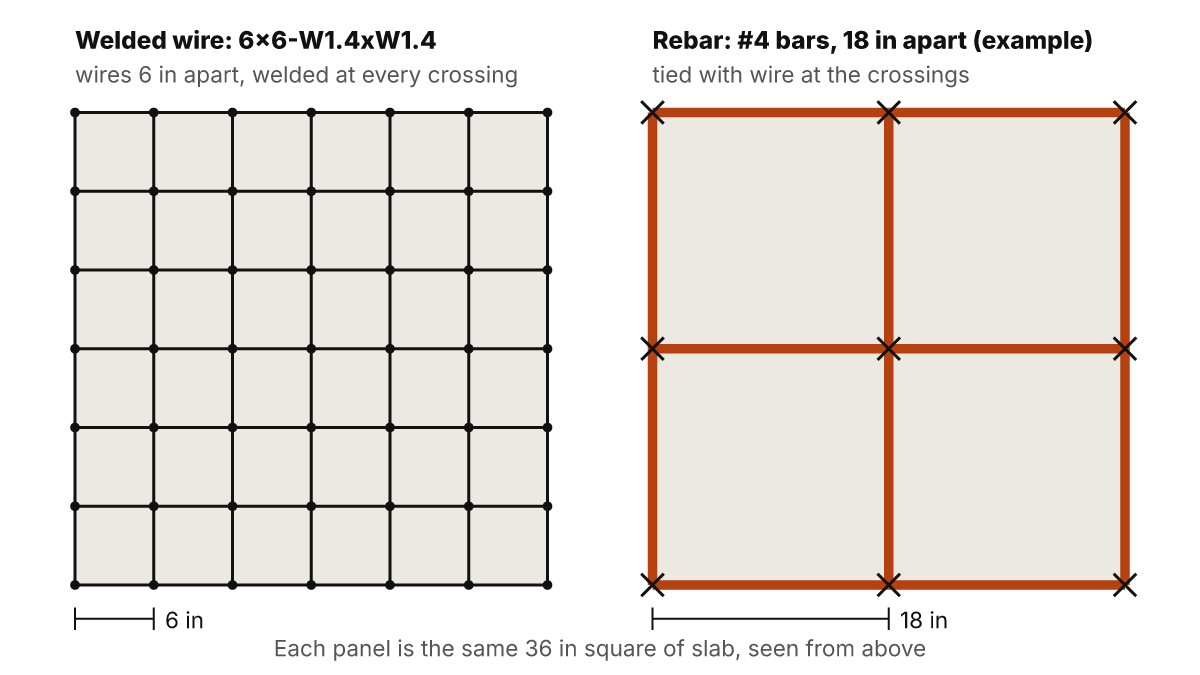
WRI's Manual of Standard Practice: “The letter ‘W’ designates a plain wire and the letter ‘D’ denotes a deformed wire. The number following the letter gives the cross-sectional area in hundredths of a square inch.” A style gives the wire spacing in both directions, then the wire sizes. So 6x6-W1.4xW1.4 means plain wires 6 in apart each way, each 0.014 sq in. Gauge numbers were replaced in the 1970s but are still common; WRI pairs two widely used styles with their old gauges:
| Style | Old gauge name | Wire spacing | Wire area | Weight |
|---|---|---|---|---|
| 6x6-W1.4xW1.4 | 6x6, 10 gauge | 6 in each way | 0.014 sq in | 0.21 lb per sq ft |
| 6x6-W2.9xW2.9 | 6x6, 6 gauge | 6 in each way | 0.029 sq in | 0.42 lb per sq ft |
Wire area is the W-number ÷ 100, per WRI's Manual of Standard Practice. Weights as published by WRI.
Rebar sizes
CRSI defines the bar number as “approximately the bar diameter in eighths of an inch,” so #4 is about 4/8 = 1/2 in. The size is rolled onto every bar, after the producing mill's mark. Caltrans publishes the standard ASTM dimensions:
| Bar | Nominal diameter | Area | Weight |
|---|---|---|---|
| #3 | 0.375 in | 0.11 sq in | 0.376 lb per ft |
| #4 | 0.500 in | 0.20 sq in | 0.668 lb per ft |
| #5 | 0.625 in | 0.31 sq in | 1.043 lb per ft |
| #6 | 0.750 in | 0.44 sq in | 1.502 lb per ft |
Caltrans's table, ASTM Standard Reinforcing Bar Data, continues to #18.
Where reinforcement sits in the slab
Steel only controls cracks if it ends up inside the slab, near enough to the top. IRC Section R506.2.4, as adopted in Seattle: “Where provided in slabs-on-ground, reinforcement shall be supported to remain in place from the center to upper one-third of the slab for the duration of the concrete placement.”
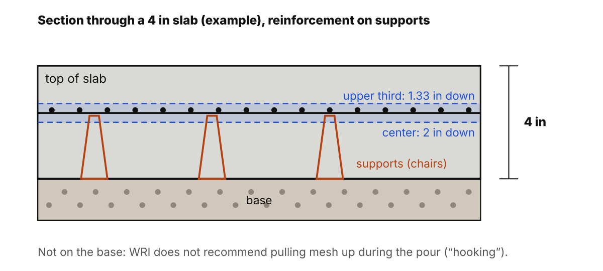
WRI's tech note on supports agrees: a single layer “should be located at or above the mid-depth of the slab,” and “in general, positioning at one-third the depth below the surface is sufficient.” Some designers require “2 inches below the top surface,” and in thicker slabs the steel must sit low enough not to interfere with saw cutting.
What doesn't work is laying mesh on the ground and pulling it up into the wet concrete (“hooking”) or pressing it in from above (“walking-in”). WRI says both are “not recommended” because “the resulting location of the reinforcing steel is approximate and can not be inspected for actual placement.”
Supports, ties, and laps
Supports for welded wire
CRSI calls chairs and blocks bar supports: “devices of formed wire, plastic or precast concrete, to support, hold, and space reinforcing bars.” From WRI:
- On soft bases such as loose sand, use supports “with base plates or with appreciable contact areas.”
- Over polyethylene sheeting, supports “must not puncture the sheeting.”
- A simple support is “a piece of concrete 2 or 3 inches thick and about 4 x 4 inches square.”
- “Common practice is to place supports 2 to 3 feet apart”; closer if the wire sags.
WRI also notes that ACI 301 “currently requires a 12″ support spacing for wire sizes smaller than D4.0 / W4.0,” while arguing spacing “should be derived on a case-by-case basis.” If your plans invoke ACI 301, the support count changes a lot, as the worked example shows.
Supports and ties for rebar
Bar supports “range from as simple as plain concrete blocks to all-plastic chairs, to wire bar supports,” says CRSI. A bar grid isn't welded: “Rebar is tied together, using wire, to hold it in place,” and the snap tie “is usually used for rebar in a flat horizontal position.”
Laps
CRSI defines a lap splice as the overlap of two bars, and “similarly the side and end overlap of sheets or rolls of welded wire reinforcement.” Bar laps come from your plans. For welded plain wire from W1.4 to W6.0 in a slab on ground, WRI's typical detail shows a 2 in minimum lap between wire centerlines, and says its use is at the discretion of a licensed design professional.
When plans or code call for it
IRC Section R506.1, as adopted in Seattle, requires slab-on-ground floors to be “a minimum 3 1/2 inches (89 mm) thick.” R506.2.4 begins “Where provided”: it says how reinforcement must be supported, not when a slab needs it.
Local codes can add a requirement. American Canyon, California, amended R506.2.4 so that slabs inside a building “shall be reinforced with not less than six inches by six inches ten-gauge welded wire mesh, or an approved alternate.” That is one city's amendment, not the model code, and it is why the building department is the first call. Beyond code, WRI lists “slab thickness, joint spacing, subgrade composition, and external loading” as the considerations in choosing a style, for the design professional to analyze using ACI 360.
Worked example: steel for a 12 × 20 ft slab
A 12 × 20 ft slab, 4 in thick, with two hypothetical plans: 6x6-W1.4xW1.4 welded wire, or #4 bars at 18 in each way, both 3 in from the edges. These are example inputs, not recommendations. Area and volume come from the concrete calculator's own formula.
Area     = 20 × 12 = 240 sq ft
Volume   = 240 × (4 ÷ 12) = 80 ft³ (2.96 yd³), before any allowance
Band     = 4 ÷ 3 = 1.33 in to 4 ÷ 2 = 2 in below the top
What the published numbers give per foot of width, each way. These are two plans worked through, not a pair to choose between; the steel a slab needs is the designer's call.
6x6-W1.4xW1.4: 12 ÷ 6 = 2 wires × 0.014 sq in = 0.028 sq in per ft
#4 at 18 in:   12 ÷ 18 = 0.67 bars × 0.20 sq in = 0.133 sq in per ft
Bars along 20 ft = 1 + 138 ÷ 18 rounded up = 9, each 19.5 ft (17.25 in apart)
Bars along 12 ft = 1 + 234 ÷ 18 rounded up = 14, each 11.5 ft
Length = 9 × 19.5 + 14 × 11.5 = 336.5 ft; weight = 336.5 × 0.668 lb per ft = 224.8 lb
Across = (138 − 2) ÷ (60 − 2) = 2.34 → 3; along = (234 − 2) ÷ (120 − 2) = 1.97 → 2
Sheets = 3 × 2 = 6 (300 sq ft); weight = 300 × 0.21 lb per sq ft = 63 lb
36 in (WRI's 2–3 ft): (1 + 138 ÷ 36) × (1 + 234 ÷ 36), rounded up = 5 × 8 = 40
12 in (ACI 301):      (1 + 138 ÷ 12) × (1 + 234 ÷ 12), rounded up = 13 × 21 = 273
Rebar: 336.5 ft × 0.20 sq in ÷ 144 = 0.47 ft³ = 0.58% of 80 ft³
Mesh:  2 × 0.028 sq in per ft × 300 sq ft ÷ 144 = 0.12 ft³ = 0.15% of 80 ft³
The sheet count treats each sheet's outermost wires as sitting at its edges; real sheets can have wire ends past the last cross wire, and your plans set the lap. Either way the steel displaces well under 1% of the slab, a small fraction of the calculator's default 10% allowance, so don't reduce the concrete order for it.
What to order
- Welded wire: the style on your plans. WRI says stock sheets are typically 5 to 10 ft wide and 10 to 20 ft long, rolls generally 5 to 7 ft wide and 150 to 200 ft long, and “sheets inherently give better placement control than rolls.” Count sheets with the laps; CRSI lists mesh cutters for cutting it.
- Rebar: the size, spacing, edge distance, and laps on your plans. Count each direction as spaces plus one, total the lengths, and multiply by the weight per foot above. Add tie wire.
- Supports: enough for the spacing your plans or specification require, with plates or a broad base on sand.
- Concrete: unchanged by the steel. For the pour, see how to pour a concrete slab, and near freezing or in heat, concrete in cold and hot weather.
Frequently asked questions
Is wire mesh or rebar better for a concrete slab?
Neither is better in general. WRI says the design process for welded wire is relatively the same as for rebar: an engineer calculates the area of steel the slab needs, then converts it to bars or to a welded wire style. Use the reinforcement your plans specify.
Does wire mesh stop a concrete slab from cracking?
No. WRI says concrete by its very nature tends to crack, and that welded wire's main job in a slab is to control cracking and crack widths, keeping the cracked sections closely knit so the slab acts as a unit. It notes that load transfer across a crack is usually ineffective once the crack is wider than 1/16 in.
Where should wire mesh sit in a 4 inch slab?
IRC Section R506.2.4, as adopted in Seattle, says reinforcement that is provided must be supported between the center and the upper third of the slab during the pour. In a 4 in slab that is 1.33 to 2 in below the top. WRI advises against laying mesh on the ground and pulling it up during the pour.
What does 6x6 W1.4xW1.4 mean?
It is a welded wire style: wires 6 in apart in both directions, both wire sizes W1.4. W means a plain wire, and the number is its area in hundredths of a square inch, so W1.4 is 0.014 sq in. WRI lists this style as the old 10 gauge, weighing about 0.21 lb per sq ft.
What size is #4 rebar?
About 1/2 in. CRSI defines the bar number as approximately the bar diameter in eighths of an inch. Caltrans's table of standard ASTM bar data lists #4 at 0.500 in nominal diameter, 0.20 sq in of area, and 0.668 lb per foot.
Does the building code require mesh or rebar in a slab?
IRC Section R506.2.4, as adopted in Seattle, says how reinforcement must be supported "where provided", not when it is needed. Local rules can go further: American Canyon, California, requires at least 6 by 6 inch, 10-gauge welded wire mesh or an approved alternate in slabs inside buildings. Ask your building department and follow your plans.
Related calculators and guides
Calculators
- Concrete Calculator — Slab volume in cubic feet, cubic yards, and cubic meters, with ready-mix order size and bag counts for documented products.
Guides
- How to Pour a Concrete Slab — Plan, form, mix, place, finish, joint, and cure a slab, following the manufacturer's published method.
- Pouring and Curing Concrete in Cold or Hot Weather — Temperature limits, freeze protection, hot-weather drying, and curing time for a new slab, with a worked example.
- Concrete Bag Yields by Bag Size — Published cubic-foot yields for bagged concrete mixes, with bags per cubic foot, cubic yard, and cubic meter.
Sources
- How to Specify, Order & Use Welded Wire Reinforcement in Light Construction (Tech Fact TF 202-R-21) — Wire Reinforcement Institute. Used for: 6x6 W1.4xW1.4 (10 gauge) 0.21 lb/sq ft and 6x6 W2.9xW2.9 (6 gauge) 0.42 lb/sq ft; stock sheets 5–10 ft wide and 10–20 ft long; rolls 5–7 ft wide and 150–200 ft long; supports commonly 2–3 ft apart; aggregate interlock usually ineffective above 1/16 in crack width; drying shrinkage 1/2–1 in per 100 ft. Checked 2026-10-06.
- Supports Are Needed for Long-Term Performance of Welded Wire Reinforcement in Slabs-on-Grade (Tech Fact TF 702-R-21) — Wire Reinforcement Institute. Used for: One layer at or above mid-depth, in general one-third of the depth below the surface; suggested support spacing 2–3 ft or less for wires smaller than W4/D4 spaced under 12 in. Checked 2026-10-06.
- Manual of Standard Practice: Structural Welded Wire Reinforcement (WWR-500-R-26) — Wire Reinforcement Institute. Used for: W = plain wire, D = deformed wire; the number is the wire's area in hundredths of a square inch (W4.6 = 0.046 sq in); a style gives the wire spacings, then the wire sizes. Checked 2026-10-06.
- Typical WPWR Lap Splice Detail, Slab-on-Ground (WWR.2) — Wire Reinforcement Institute. Used for: 2 in minimum lap splice, measured between wire centerlines (drawn between the outermost wires of the two mats). Checked 2026-10-06.
- Welded Wire Reinforcement: Frequently Asked Questions — Wire Reinforcement Institute. Used for: Wires up to 5/8 in diameter (equivalent to a #5 rebar); ACI 301 support spacing of 12 in for wires smaller than D4.0/W4.0. Checked 2026-10-06.
- Reinforced Concrete Terminology — Concrete Reinforcing Steel Institute (CRSI). Used for: Bar number ≈ bar diameter in eighths of an inch (#5 ≈ 5/8 in). Checked 2026-10-06.
- Reinforcing Bar Placing — Concrete Reinforcing Steel Institute (CRSI). Checked 2026-10-06.
- Bar Identification — Concrete Reinforcing Steel Institute (CRSI). Checked 2026-10-06.
- Bridge Design Details 13.1, Reinforcement: Table 13.1.1, ASTM Standard Reinforcing Bar Data (September 2025) — California Department of Transportation (Caltrans). Used for: #3: 0.375 in, 0.11 sq in, 0.376 lb/ft; #4: 0.500 in, 0.20 sq in, 0.668 lb/ft; #5: 0.625 in, 0.31 sq in, 1.043 lb/ft; #6: 0.750 in, 0.44 sq in, 1.502 lb/ft. Checked 2026-10-06.
- 2015 Seattle Residential Code, Chapter 5 Floors: Section R506, Concrete Floors (On Ground) — City of Seattle, Department of Construction and Inspections. Used for: Slab-on-ground floors at least 3 1/2 in thick; reinforcement, where provided, supported from the center to the upper one-third of the slab during placement. Checked 2026-10-06.
- American Canyon Municipal Code 16.03.070: Amend Section R506.2.4 Reinforcement support — City of American Canyon, California. Used for: Slabs inside a building reinforced with at least 6 × 6 in, 10-gauge welded wire mesh or an approved alternate. Checked 2026-10-06.